MATTHEW JOVERO
Note: Although this website is accessible through a mobile device, its layout and overall experience is better on a laptop or desktop.
SUMMARY
Thanks for stopping by! Whether you're here to analyze, explore, or get inspired, I hope my work sparks your curiosity.
Strengths:
Addicted to CAD-modeling.
If I don't know how it works, I will find out (eventually).
Calm during stressful engineering situations.
Weaknesses:
Addicted to CAD-modeling.
Productivity is directly proportional to caffeine intake.
Not calm when Wi-Fi drops.
EXPERIENCE

MY JOURNEY

Sep 2024 - Dec 2024
SENSITIVITY ANALYSIS
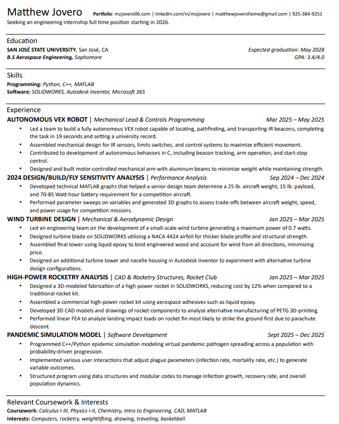
Conducted sensitivity studies on a competition aircraft to determine ideal design choices and competition strategies for a senior design team.
Read More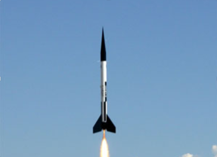
Jan 2025 - Mar 2025
HIGH-POWER ROCKETRY ANALYSIS
Conducted comparative analysis between traditional kit rockets and 3D-printed alternatives using SOLIDWORKS.
Read More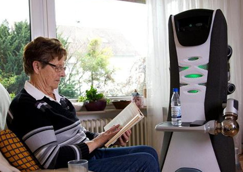
Mar 2025 - May 2025
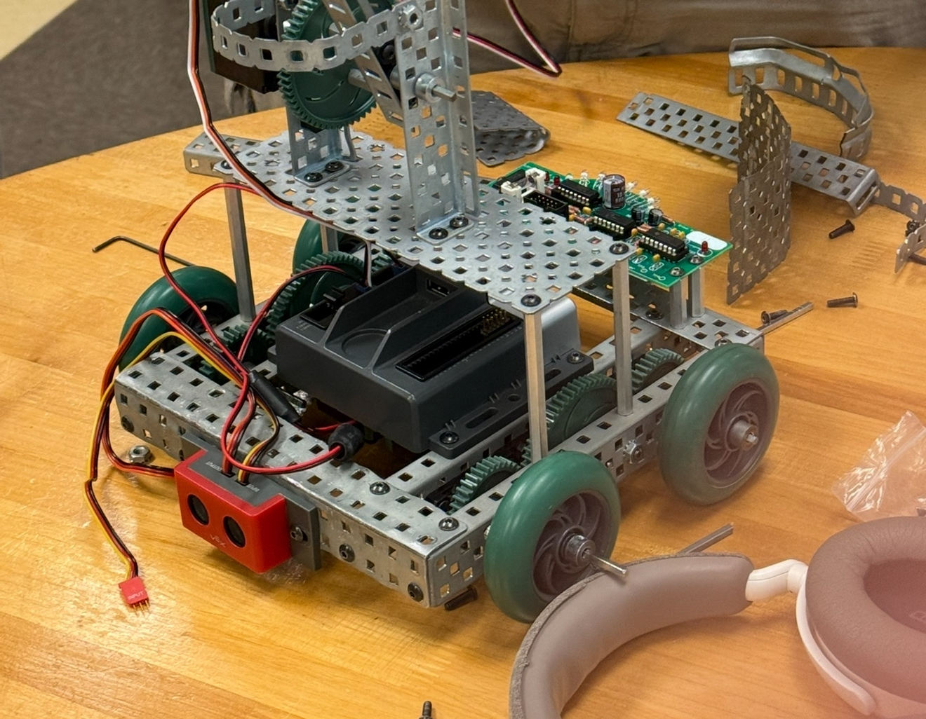
AUTONOMOUS ROBOT
Led the mechanical design and program of an autonomous robot capable of interacting with infrared beacons.
Read More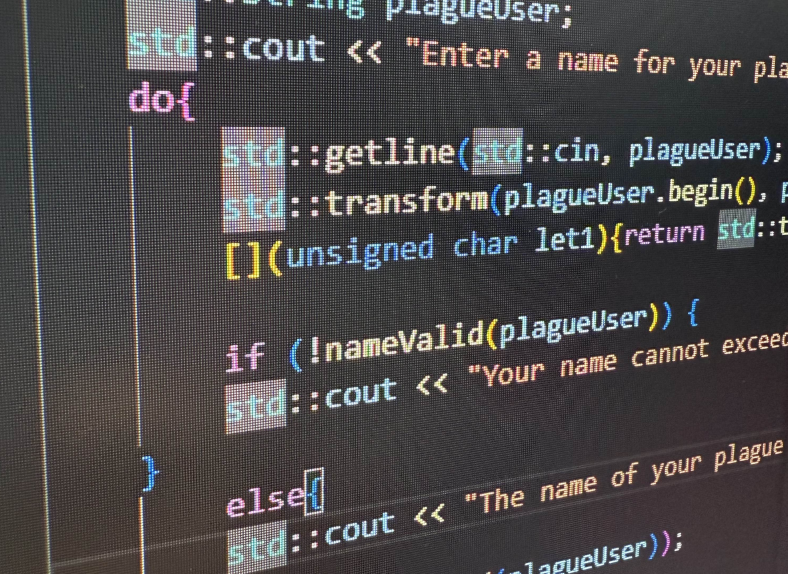
Aug 2025 - Dec 2025
PANDEMIC MODEL
C++/Python model replicating the spread of a global pandemic with variable user outcomes.
Read More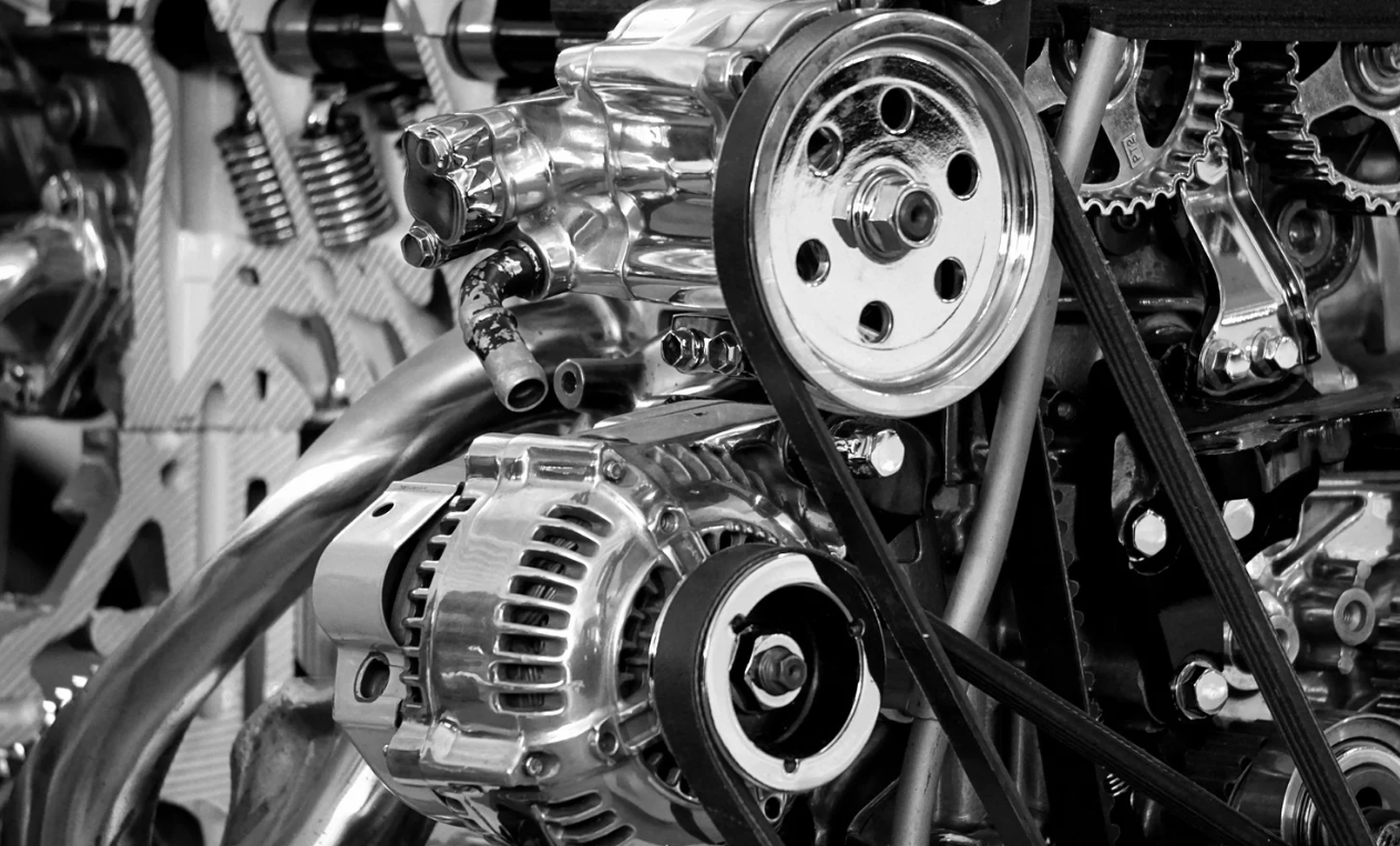

Email: matthewjoverohome@gmail.com

PROJECTS
Click on a picture to learn more!


Email: matthewjoverohome@gmail.com

ABOUT ME
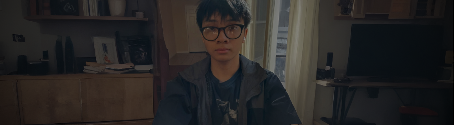
Hi there! My name is Matthew Jovero and I'm currently in my sophomore year as an engineering student at San José State University. Having always lived in the bay area, my passion for engineering and technology came from a 13-year old boy being interested in assembling paper origami parts.
Currently, I am planning to begin a new CAD project this December that will go on into the new year! If you'd like to see how my curiosity grew into real engineering experience, you can learn more about my journey on my resume:
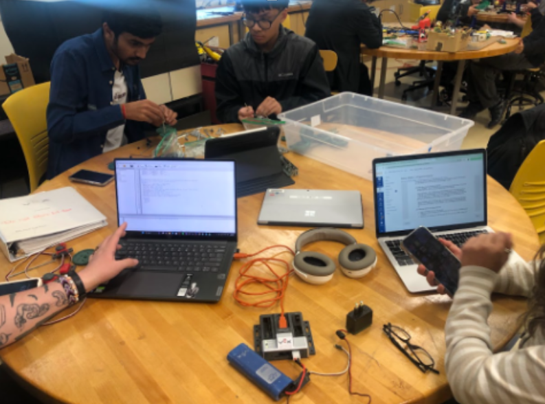
My team and I building a fully autonomous robot
Email: matthewjoverohome@gmail.com

CONTACT
LET'S TALK
Email: matthewjoverohome@gmail.com
Telephone: 925 - 384 - 9251
LinkedIn: linkedin.com/in/mzjovero
Email: matthewjoverohome@gmail.com

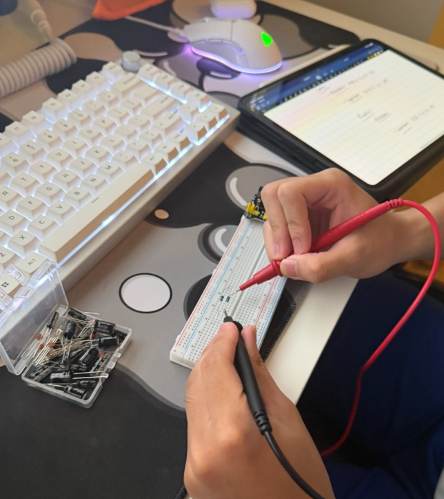
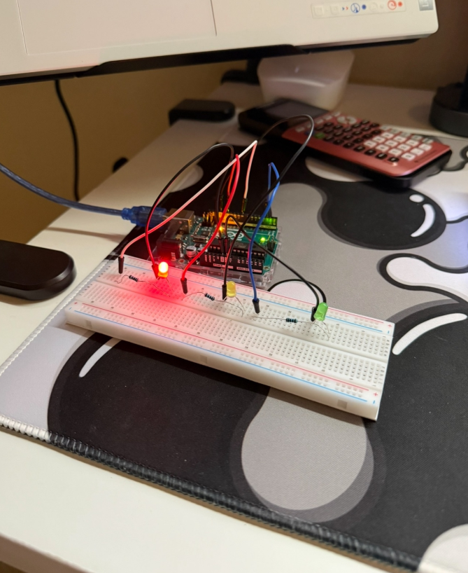
AUTONOMOUS ROBOT
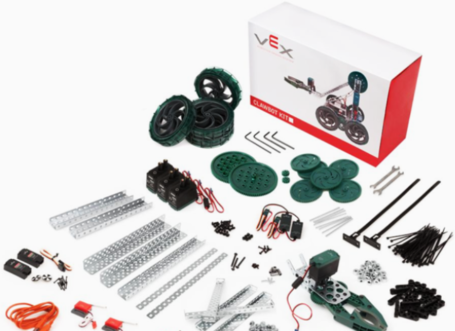
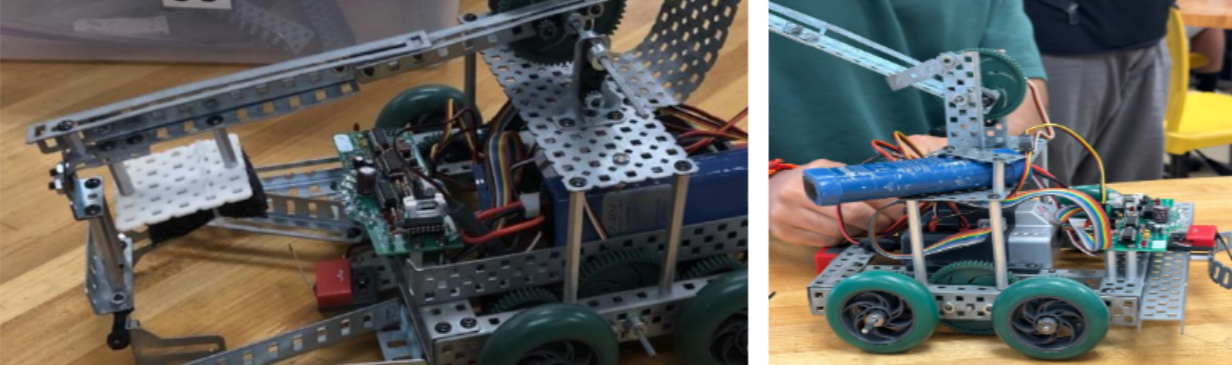
I partook in a team project to design and build a fully autonomous VEX companion robot with the capability of a domestic task: Turning off a stove and bringing a plate to another room. As the mechanical lead, I was in charge of assembling the robot's chassis frame and implementing a functioning single-axis arm design in the span of six weeks, taking into account a weight restriction.
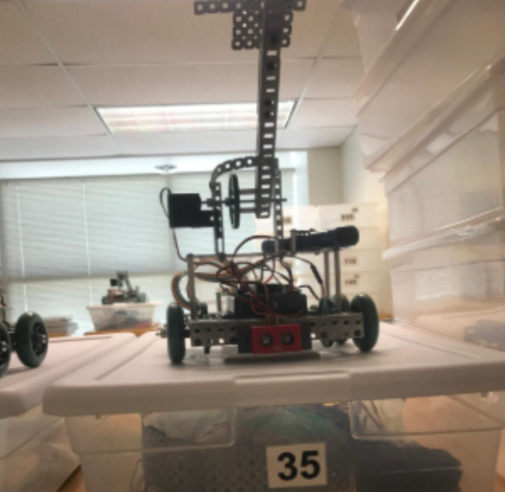
Mechanical parts consisted mainly of aluminum beams, which are lightweight yet strong in order to minimize final weight. Additionally, I contributed to C-programming of the autonomous behaviors, system testing and troubleshooting, and writing a final technical report. Our completed robot was able to complete the task in 19 seconds, setting a university record.
Incase the YouTube embed is blocked: https://youtu.be/31GKb08b29w

Email: matthewjoverohome@gmail.com
SENSITIVITY ANALYSIS
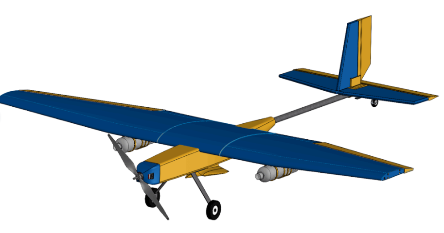
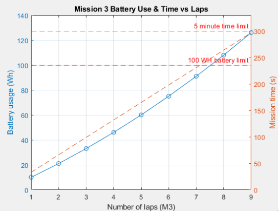
I had the unique opportunity of conducting a sensitivity analysis for a senior design team who were building an aircraft for an annual AIAA Design/Build/Fly competition. Although I was not a direct competition member, I played a key role in helping the team evaluate optimal aircraft design parameters and competition strategies.
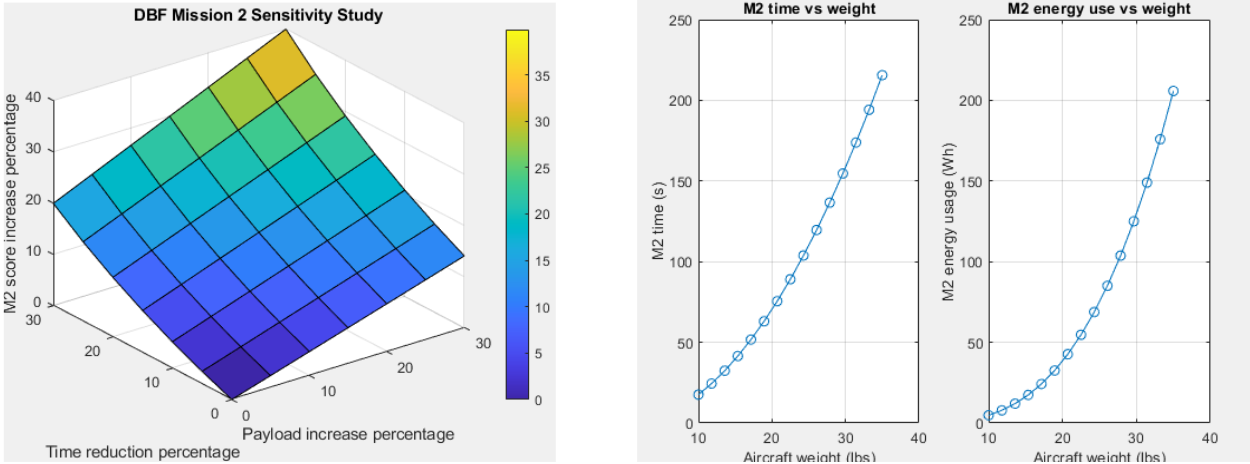
The sensitivity study was conducted utilizing MATLAB and noting competition equations that impacted the score. I used a parameter sweep technique to see how changing certain design variables impacted the score and overall aircraft performance. I helped the team determine a 25 lb. total aircraft weight, a 15lb. total payload weight, a 70-85 Watt-hour battery performance, and other additional performance-driven strategies.

Email: matthewjoverohome@gmail.com
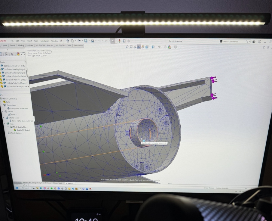
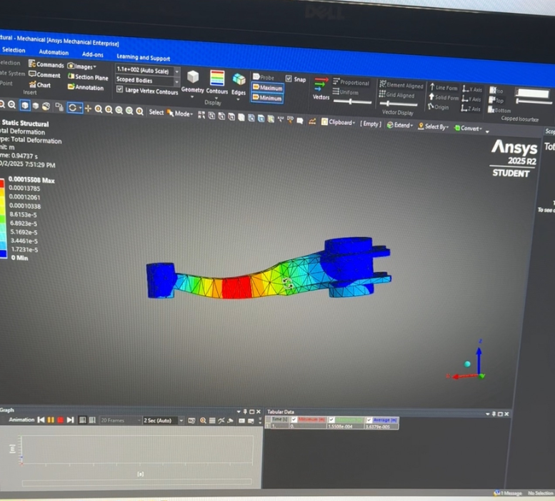
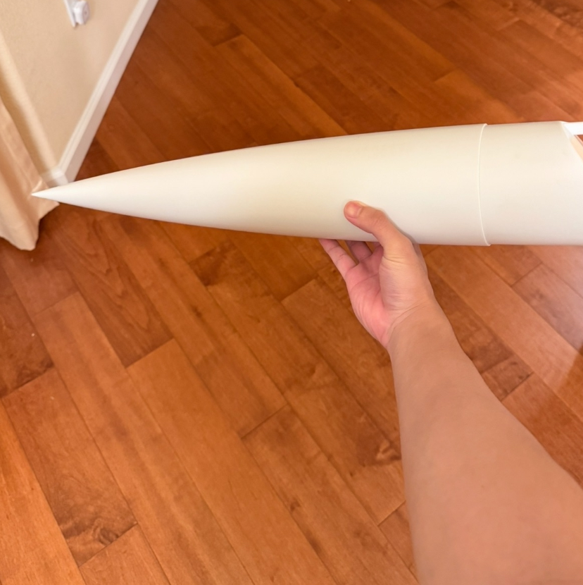
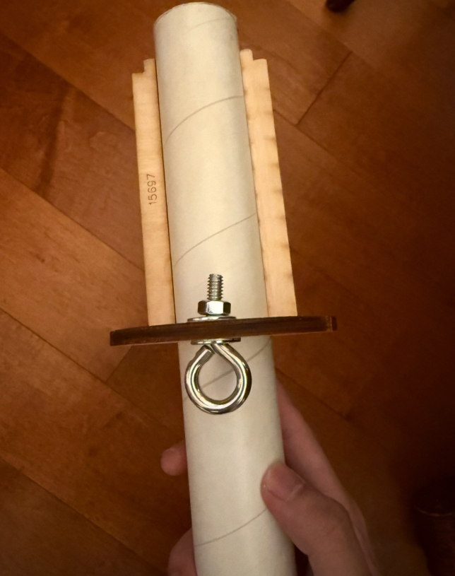
ROCKETRY ANALYSIS
I have always been interested in rocketry and 3D-modeling. I began a personal project comparing a high-power rocket from a traditional kit to a fully 3D-printed one with PETG using SOLIDWORKS. This project also included the physical assembly of a traditional rocket kit with aerospace adhesives such as epoxy.
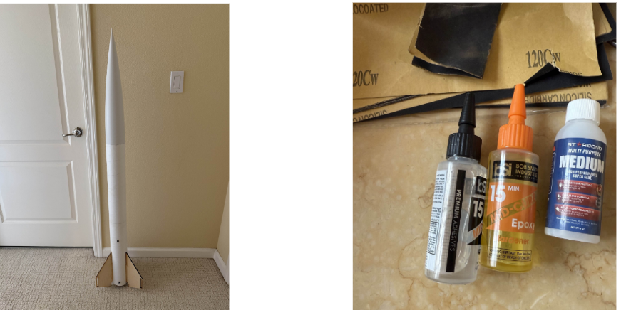
Due to how the rocket connects to the parachute once it deploys, the fin opposite to the eye-bolt hole of the front-centering ring will always strike the ground first at landing. I conducted finite element analysis on this fin to see how its landing reacts with PETG material properties.
Additionally, to compare cost, I included all significant middle-end materials and recorded a percentage difference of 11.6% in favor of the 3D-printed fabrication.

Email: matthewjoverohome@gmail.com
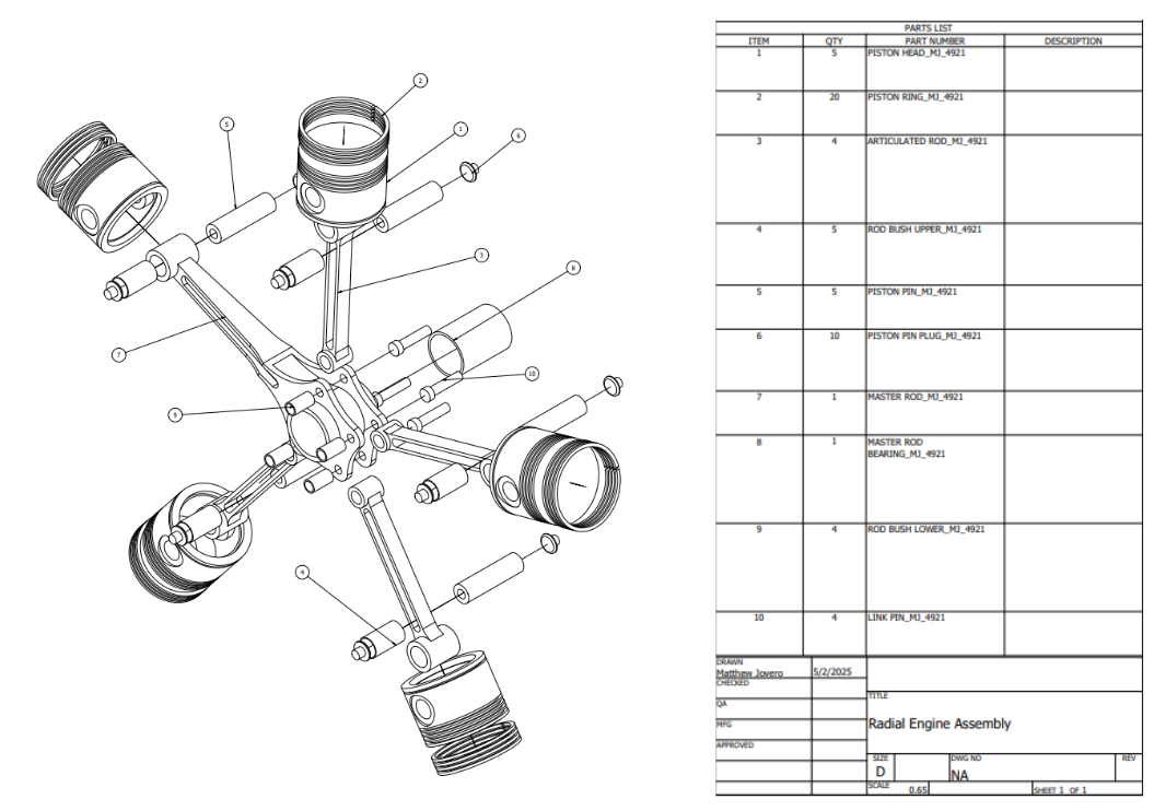
RADIAL ENGINE
In my computer aided design course, I designed a radial engine that you would typically see from an aircraft during the piston-engine era using Autodesk Inventor.
Material consisted of steel AISI 4340 242 HR for bearings and plugs. Significant design challenges include intricate details in the piston head and master rod parts.

Email: matthewjoverohome@gmail.com
PANDEMIC MODEL
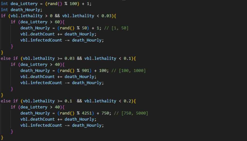
During the summer, I decided to initiate a software project by developing two versions of a pandemic simulation minigame using C++ and Python.
The game models the spread of a disease across a population, requiring players to strategically manage timing and upgrades. The goal of the game is to spread your plague across the entire country before doctors find a cure for it!
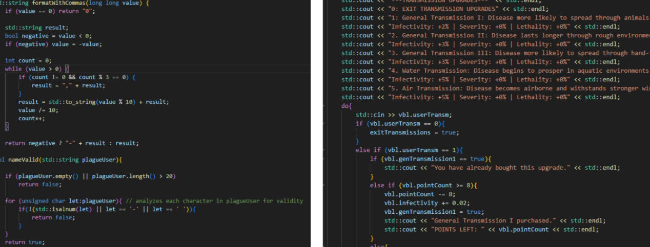
The format of the program utilizes data structures to track parameter values and relationships. These values change over time through a probability-based logic system and point system where the player can purchase upgrades for their plague and slow down humanity's response. The Python version consists of different abilities for your plague that can help you advance further into the game.
Project challenges include properly syncing plague stats with population scaling to guarantee balanced and realistic progression.
In case the YouTube embed is blocked: https://youtu.be/NI7moMOjPAw

Email: matthewjoverohome@gmail.com
RANDOM THINGS
You don't need words to tell a story that pictures already do for you... (more coming!)
Email: matthewjoverohome@gmail.com
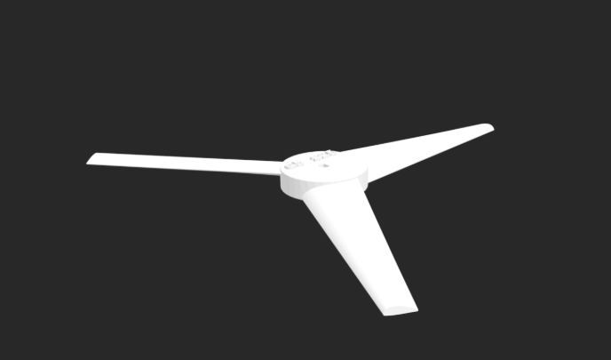
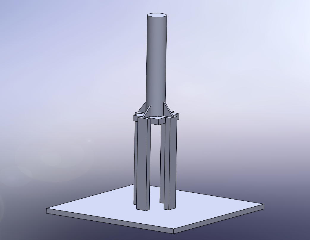
WIND TURBINE
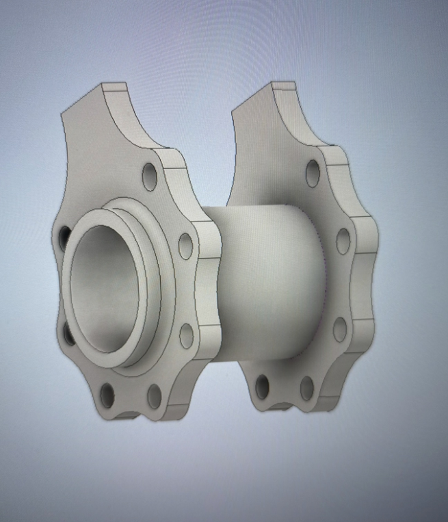
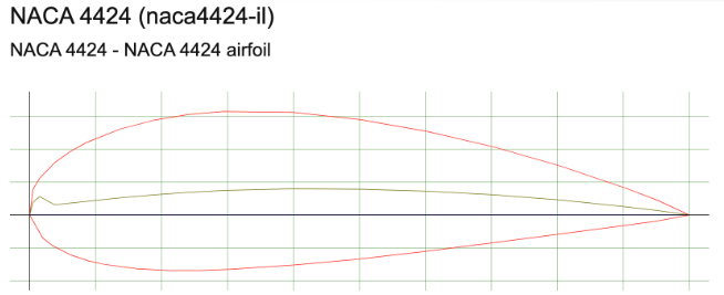
I helped design a wind turbine blade and tower for an engineering team. We decided to implement three blades around this hub with the NACA 4424 airfoil and an angle of attack of 45 degrees. This decision was to increase structural strength for a smaller-scale wind turbine more vulnerable to vigorous winds.
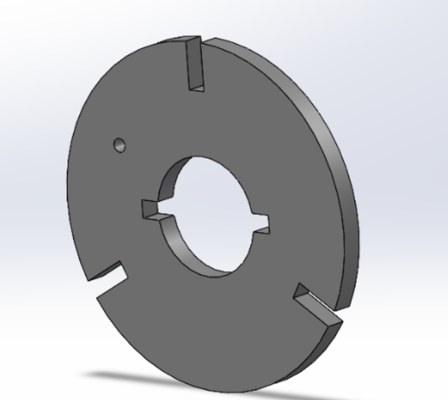
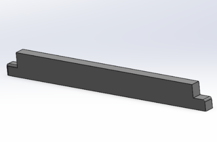
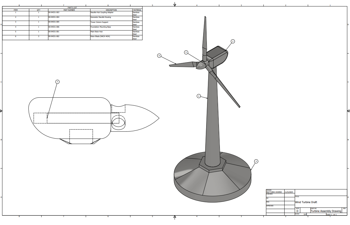
The CAD drawing below shows an alternative tower design I made using Autodesk Inventor with a nacelle-style housing designed for where the gear box would be. This design accounted for winds from all directions and structural support for the hub.
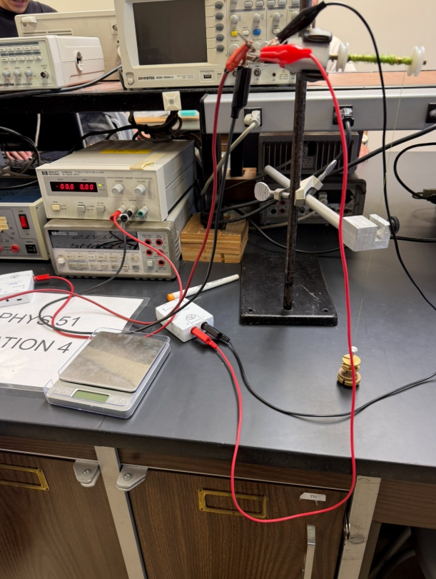
The last picture shows our actual turbine design used during testing. This design consisted of engineered wood binded with liquid epoxy and screws, which was all binded by a 508 mm x 508 mm default wooden plate. Our design methodology was to prevent significant deformation during the stiffness test. Testing results came out with a maximum generated power of 0.7 W, height of 438 mm, weight of 0.245 kg, and stiffness of 9.81 N per mm.

Email: matthewjoverohome@gmail.com
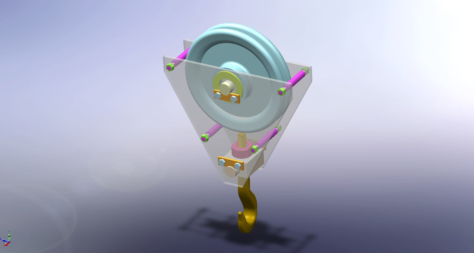
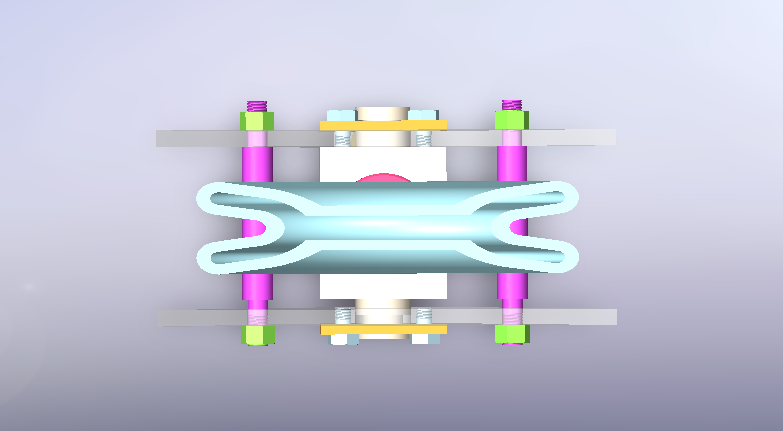
PULLEY CRANE SYSTEM
I designed a detailed pulley crane system using SOLIDWORKS, taking for account long-term stress loads for better functionality.
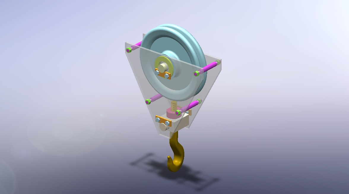
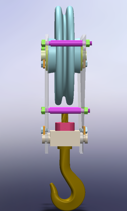
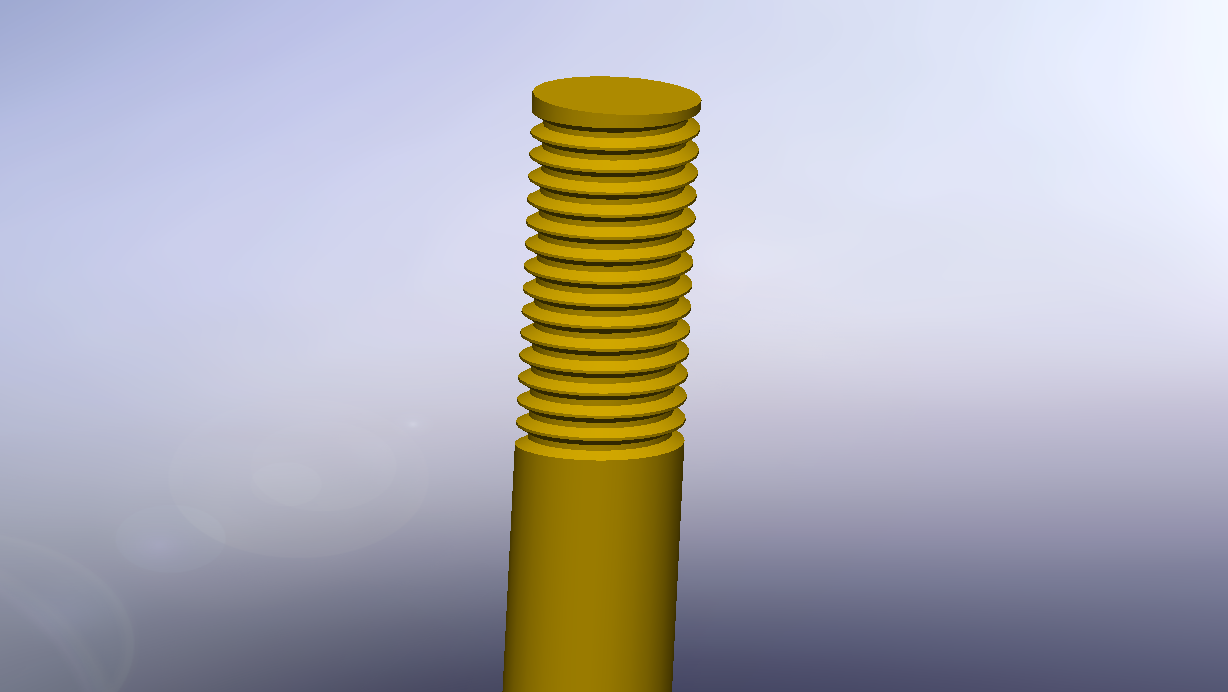
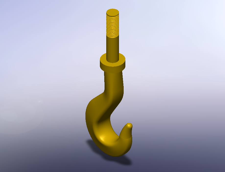
Multiple fillets were distributed to different parts of the pulley assembly to reduce concentrations of stress. I designed the top interface of the took with a metric fine threaded shank of M20 x 0.5 for secure attachment and realistic detailing of the hardware.
Challenges included curvature of the hook, deciding on realistic proportions, and different mating relationships during assembly.

Email: matthewjoverohome@gmail.com